• HV37-15F  Fast Recoveryhigh voltage diode 15KV, 250mA, 75nS
  • HV37-15F  Fast Recoveryhigh voltage diode 15KV, 250mA, 75nS
  • HV37-15F  Fast Recoveryhigh voltage diode 15KV, 250mA, 75nS
  • HV37-15F  Fast Recoveryhigh voltage diode 15KV, 250mA, 75nS
  • HV37-15F  Fast Recoveryhigh voltage diode 15KV, 250mA, 75nS
  • HV37-15F  Fast Recoveryhigh voltage diode 15KV, 250mA, 75nS

HV37-15F Fast Recoveryhigh voltage diode 15KV, 250mA, 75nS

No.HV37-15F
Products Main features:
1、Axial leaded connection.
2、High thermal conductivity epoxy compound molding.
3、Fast Reverse Recovery Time for High Efficiency.
4、Special passivation glue chip protection
5、Excellent discharge characteristics.
  • HV37-15F  Fast Recoveryhigh voltage diode 15KV, 250mA, 75nS
  • HV37-15F  Fast Recoveryhigh voltage diode 15KV, 250mA, 75nS
  • HV37-15F  Fast Recoveryhigh voltage diode 15KV, 250mA, 75nS
  • Desciption

  • data sheet

  • Package Size

  • Installation Guide

Product Overview

A 15 kV fast recovery diode in an axial package, this part is built for rectifier circuits in high-voltage supplies. The body is a black cylindrical moulding about 15 mm long and 4.5 mm across, with a white band at the cathode end and two straight leads; inside, the chip sits under a passivation adhesive layer and the whole assembly is encapsulated in a high-thermal-conductivity epoxy compound. That combination — small body, protected chip, heat-conducting encapsulant — is what makes a 15 kV part practical to mount on a board or drop into an oil-filled tank.

Within the HV37 family this is the highest-voltage member, and the trade-off shows up in the current ratings: as reverse voltage rises, the average current the same body can pass falls. Designs that need the full 15 kV of margin sit here. Designs that need 350–500 mA usually step down to the 10 kV or 6 kV models and accept a lower reverse voltage, or move to a larger rectifier assembly.

High voltage diodes of this class work in the rectifier stages of medical imaging generators, industrial NDT and X-ray equipment, HVDC and electrostatic supplies, high-voltage test sets and radar modulators. The same part is the usual replacement when a legacy axial diode on an existing high-voltage board fails or goes obsolete: the axial format, the lead arrangement and the cathode band are the familiar ones, so a substitution is a question of ratings rather than of re-machining the mounting.

Key Features

  • In a high-frequency high-voltage supply that shows up as lower recovery loss and less heating inside the device. - High-thermal-conductivity epoxy moulding — the encapsulant carries heat from the chip to the body wall and on into oil, gas or air, which is why a body this small can pass a useful current at all. - Passivation adhesive over the chip — an insulating adhesive layer covers the chip surface before moulding and holds back surface leakage and breakdown at high field. A part this compact leans on that layer for its voltage hold. - Surge headroom — the surge rating covers the inrush pulse of a capacitor charging through the rectifier, so the diode rides out the switch-on event that a marginal part fails on. - Stable discharge behaviour — characterised for discharge duty as well as rectification, so capacitor-discharge and pulse-forming circuits do not see an unpredictable recovery tail. - Marked cathode, straight axial leads — the white band identifies the cathode end, and the straight leads suit through-hole and point-to-point wiring without special tooling.

Specifications

ParameterSymbolTest conditionValue
Repetitive peak reverse voltageVrrmTa = 25 °C, Ir = 2.0 µA15 kV
Average forward current, in airIf(AV)Ta = 40 °C, in air250 mA
Average forward current, in oilIf(AV)Ta = 55 °C, in oil150 mA
Reverse recovery timeTrr-75 ns
Surge forward currentIfsm0.01 s half-sine, 50 Hz15 A
Forward peak voltageVfm-≥ 24 V
Reverse leakage currentIrrm1Ta = 25 °C, VRM = VRRM2.0 µA
Reverse leakage currentIrrm2Ta = 100 °C, VRM = VRRM10.0 µA
Operating ambient temperatureTa--55 to +125 °C
Storage temperatureTstg--55 to +125 °C
Package-Axial leaded, HVD-415See package dimensions

Package & Dimensions

  • Body diameter (φ1) — 4.5 mm (0.18 in) with a ±0.2 mm tolerance, so allow for the moulding when you set clearance to nearby metal.
  • Body length (L1) — 15 mm (0.59 in), ±0.2 mm.
  • Lead diameter (φ2) — 0.8 mm (0.03 in), ±0.2 mm; a standard through-hole drill and a normal soldering iron will handle it.
  • Lead dimension (L2) — 25 mm (0.98 in). This one carries the wider ±0.5 mm tolerance, so set your mounting centres from it rather than from the body length.
  • Package code HVD-415, straight-lead outline — the drawing shows the straight-lead form with the cathode band at one end. Keep parts in their labelled packaging until assembly; a high voltage diode this small is easy to mix up on a bench.
  • No type number on the moulding — apart from the cathode band the body is unmarked, so identify a loose part by its packaging or by measuring it, never by reading the body.
  • Lead forming — support the lead between the bend and the body seal, bend once, and avoid repeated flexing at the same point.

Operating Medium & Insulating Adhesive

Choosing the medium

The two current ratings on the datasheet are not a like-for-like pair, and reading them as one is the most common mistake with a part this size. Oil immersion lets the diode live in a hotter environment, but the higher ambient costs current — so decide the medium first, then read the rating that goes with it. Four arrangements are used in practice. Immersing high voltage diodes in insulating oil is recommended, and so is mounting them in insulating gas; both media suppress corona and carry heat away from the body. Secondary packaging — potting or encapsulating the assembly — also works, but it leans harder on the diode's own heat path, so leave more current margin. Running in exposed air is the least forgiving option: a small high-voltage part in air discharges easily and sheds heat poorly, so add forced air cooling where you can, fit insulated electrodes at both ends, and keep the working voltage below the rated 15 kV with real margin. Treat 125 °C as a design limit rather than a target: the epoxy encapsulant and the passivation layer are what set it. Choosing the insulating adhesive

Most assemblies bond the diode body or its leads down with an insulating adhesive, and the material changes how that joint behaves over life. Silicone cures to a clear, elastic rubber. It absorbs shock and rides out the severe stress of large hot-cold swings, and it is the natural choice where the assembly will see temperature excursions. Acrylic cures clear and hard, takes up little moisture, sets quickly and gives strong wear and insulation performance. Urethane also cures clear and hard, wears well and resists moisture; it is particularly stable at low temperature but less tolerant of heat. Epoxy is the rigid option — usually opaque, very sturdy, resistant to moisture, chemicals and wear, with good dielectric properties. Match the adhesive to what the joint has to survive: thermal cycling supports silicone, a fast rigid bond to acrylic, low-temperature service to urethane, and chemical or moisture exposure to epoxy. Cure it fully before the first high-voltage test.

Installation Sequence

  1. Inspect before assembly — check the leads are straight and the body free of cracks or chipped epoxy. On a fast recovery diode this small the leads are the only mechanical interface, and a lead bent hard against the seal is a leak path waiting to happen.
  2. Set the orientation from the cathode band — the band marks the cathode, which in a rectifier leg faces the DC output side. Reversed, the diode conducts on the wrong half cycle and fails at the first full-voltage event.
  3. Form the leads with support — grip the lead between the bend and the body, bend once, and keep the radius outside the seal area.
  4. Keep high-voltage clearance — in a high voltage diode this small, distance is insulation. Hold the body and leads away from earthed metal and from other high-voltage nodes; tight layouts are where discharge starts.
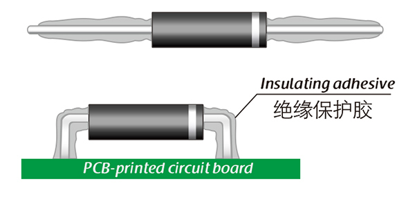
  5. Bond with the insulating adhesive — apply it to the body or the board as your assembly drawing requires and let it cure fully before test. A partly cured adhesive insulates far less than a cured one.
  6. Fit insulated electrodes if the part runs in air — where the assembly is not oil- or gas-filled, terminating both ends with insulated electrodes keeps corona at the lead exits under control.
  7. Bring it up on a current-limited supply — raise the voltage in steps and watch reverse leakage at the working temperature, not just cold. A part that leaks more than expected when warm is telling you the thermal path is wrong.

HV37 Series Range

ModelVrrmForward current in air (40 °C)Forward current in oil (55 °C)Forward peak voltage
HV37-06F6 kV500 mA300 mA≥ 12 V
HV37-08F8 kV400 mA210 mA≥ 14 V
HV37-10F10 kV350 mA190 mA≥ 16 V
HV37-12F12 kV300 mA170 mA≥ 19 V
HV37-15F15 kV250 mA150 mA≥ 24 V

Ordering & Delivery

  1. Start from the ratings — reverse voltage, forward current at your medium and ambient, recovery time and the L2 mounting dimension. If you are replacing an existing part, quote the number printed on it; high voltage diode manufacturers can match a part from that number far more reliably than from a photograph of the board.
  2. Ask about sample availability and lead time — your sales contact will confirm whether samples of this model are available and what the current lead time is for the quantity you need.
  3. Confirm the packing for your line — tell us whether the parts will be hand-soldered from a bag, fed from tape or presented in a tray, and we will confirm what is available for this model.
  4. Shipping — International express. Confirm the destination, consignee and any labelling your goods-in team needs at quotation stage.
  5. Payment and documents — payment terms and the paperwork you require are agreed with your sales contact when the order is placed.
  6. Inspect on arrival — check lead straightness, body condition and the quantity against the packing list before the parts go into stores. Axial leads can bend in transit; catch it before assembly rather than at the test bench.
  7. Keep the technical contact open — the same contact handles questions on mounting, adhesive choice or a diode that runs hot after commissioning. Raise it there rather than guessing at a fix.

Technical Support & Model Matching

Selection starts with your circuit, not a catalogue number: tell us the working voltage, load current, switching frequency and ambient cooling conditions, and our engineers will match a model from our range and explain the margin left in the design. Each model ships with its datasheet, package drawing and installation guide, and we stay available for mounting and soldering questions, start-up checks and fault finding when an existing part runs hot or fails early. Orders run from about 7 days to 6 months depending on quantity, usually by international express.

FAQ

What forward voltage drop should I design for?

The datasheet lists forward peak voltage Vfm as ≥24 V, which is high next to a low-voltage rectifier and follows from the construction: a 15 kV diode is a stack of series junctions, and each one adds its drop. High voltage diode manufacturers trade forward voltage for reverse voltage, so build your loss budget on the listed figure rather than on a single-junction 0.7 V, and ask us for the value at your operating current if you need it.

Does this diode need a heatsink?

No. There is no tab and no heatsink to fit: this high voltage diode sheds heat through the epoxy into the body wall and through the leads into the board and the surrounding medium. That is why the current rating changes with the medium — in air, treat the copper the leads are soldered to as part of the thermal path and keep those joints short.

What reverse leakage should I expect at temperature?

Reverse leakage at the rated reverse voltage is listed as 2.0 µA at 25 °C and 10.0 µA at 100 °C. Take the 100 °C figure for your worst-case error budget on a 15 kV rail, and measure leakage at the temperature the part will actually reach — a cold measurement tells you very little about a diode sitting in a warm enclosure.

How does this compare with the surface-mount PF diodes?

This model is axial leaded: a cylindrical body, two straight leads and a marked cathode, made for through-hole or point-to-point wiring and for potting or oil immersion. High voltage diodes in the PF series use a surface-mount gullwing package for densely populated boards. Choose on how the assembly is built first; the ratings decide the rest.

How can I check a delivered batch against the datasheet?

The figures incoming inspection usually re-checks are recovery time, reverse leakage and forward peak voltage. Our benches include a TRR tester, a high-voltage test bench, a leakage current tester and a high-low temperature chamber, so those parameters can be measured rather than assumed. High voltage diode manufacturers are judged on whether the delivered part matches the sheet, so ask your sales contact for measured data if your procedure needs it.

Is 15 kV a peak figure or a continuous DC rating?

It is the repetitive peak reverse voltage, quoted at 25 °C — a repetitive peak, not an average DC working level. Design the rail so the worst repetitive peak you can reasonably expect, transients included, stays below it. A diode run at its rated peak with no margin is a diode waiting for the first surge.

The selection of high-voltage diodes is closely related to their usage environment。

1. Used in insulating oil. (Recommended)
2. Used in insulating gases. (Recommended)
3. Secondary packaging use. (High requirements for heat dissipation and other parameter performance of components)
4. Use in exposed air or add air cooling. (If the size of the high-voltage diode is small, it is easy to discharge, and the heat dissipation performance is average.)

For high-voltage diodes used in exposed air, it is recommended to install them with insulated electrodes at both ends.


Common treatment methods for surface adhesive insulation:

Characteristics of insulation adhesive material:

1. Silicone material usually presents a transparent and elastic rubber state after curing, which is more effective in shock resistance and can also withstand severe stress changes caused by large high and low temperature changes (-40 ° C~200 ° C).

2. Acrylic materials typically exhibit a transparent and hard coating after curing, with low moisture absorption and fast curing time, as well as excellent wear resistance and insulation.

3. After curing, Urethane material usually presents a transparent and hard coating, which has superior wear resistance and good moisture resistance. Its performance is particularly stable in low temperature environments, but it is less resistant to high temperatures.

4. The coating material based on epoxy is very sturdy and usually opaque, with good moisture and moisture resistance. Its resistance to chemical corrosion and wear is also very good. In addition, epoxy also has good dielectric properties.

Here, suitable insulation adhesive materials can be selected based on the different usage situations of engineers.

HVDIODE - Suly Electronics Co., Ltd.

Expects To Provide You With Perfect Service

Name
Email *
Verification Code *
Click to verify
Leave a message
Name
Email *
Message
Verification Code *
Click to verify
We use Cookie to improve your online experience. By continuing browsing this website, we assume you agree our use of Cookie.