At 8 kV the mechanical drawing is part of the electrical design, not paperwork. The specified body and lead dimensions set the envelope, and general tolerances are ±0.2 mm with a wider ±0.5 allowance on lead length, so a formed lead can end up slightly longer or shorter without forcing a layout change.
The body length is doing real work. It sets the distance between the two points where the leads leave the moulding, which is the surface path the voltage has to cross when the part runs in air. Shorten that body and you shorten that path, which is why a part of this voltage class cannot simply be scaled down.
The lead length gives you room to reach through a board, form a foot for surface mounting, or trim after soldering. The drawing shows both straight leads and formed leads bent for PCB mounting, with the joint covered by insulating adhesive — the arrangement most assemblies use for an axial lead high voltage diode.
Keep the body clear of metalwork, screw heads and neighbouring traces, and treat the coating as part of the insulation system rather than an optional extra. Check the drawing before you finalise a tight footprint: the tolerance on lead length is wider than on the body, and that changes how a formed lead seats in a plated hole.
An 8 kV, 400 mA fast recovery rectifier turns up wherever a supply has to generate a few kilovolts at modest current and switch quickly while doing it. The everyday example is the high-voltage generator in imaging equipment — X-ray tubes, digital radiography, CT and dental panoramic units — where rectification sits after a step-up transformer or inside a multiplier and the diodes have to stay cool in a small enclosure.
Industrial imaging and test equipment uses the same class of part: non-destructive testing sets, cable and insulation testers, high-voltage calibration benches, electrostatic and HVDC supplies, and radar modulator circuits. In each of them the high voltage diode is one link in a chain, and its recovery time and leakage decide how much of the design margin is left for everything else.
Smaller builds put the part in a PCB-mounted multiplier string, where the axial body is formed flat against the board and the whole assembly is then coated or potted for insulation. That arrangement suits this package well, provided the coating is applied without voids and the board keeps its distance from other conductors.
If your rail is lower and your current higher, or your working voltage is well above this step, a different model in the same family fits better without changing the board outline.
| Parameter | Rating and test condition |
|---|---|
| Repetitive peak reverse voltage (Vrrm) | 8 kV at Ta = 25 °C, Ir = 2.0 µA |
| Average forward current in air (If) | 400 mA at Ta = 40 °C |
| Average forward current in oil (If) | 210 mA at Ta = 55 °C |
| Reverse recovery time (Trr) | 75 ns |
| Surge forward current (Ifsm) | 15 A for 0.01 s, half-sine, 50 Hz |
| Forward peak voltage (Vfm) | ≥ 14 V |
| Reverse leakage (Irrm) | 2.0 µA at Ta = 25 °C and 10.0 µA at Ta = 100 °C, VRM = VRRM |
| Operating ambient temperature (Ta) | -55 to +125 °C |
| Storage temperature (Tstg) | -55 to +125 °C |
| Package code | HVD-415 |
| Body diameter (D) | 4.5 mm / 0.177 in |
| Body length (L1) | 15.0 mm / 0.591 in |
| Lead diameter (d) | 0.8 mm / 0.031 in |
| Lead length (L2) | 25 mm / 0.98 in |
Reverse leakage is the current that keeps flowing while the diode is blocking, and it is the parameter that decides whether an 8 kV node holds its voltage once the junction is hot. The HV37-08F is specified at 2.0 µA with the full 8 kV across it at 25 °C, and at 10.0 µA at 100 °C. The hot figure is the one to design with in any circuit that runs warm, because leakage rises steeply with junction temperature and a part that measures clean on a cold bench can still load a high-impedance node after warm-up.
In a high-impedance high-voltage node — a multiplier stage, a bias or clamp feed, a low-current divider — that leakage behaves like a resistor connected across the diode. A few microamps can pull down a node fed through a high-value resistor, shift a threshold, or add an error that only appears after the assembly has reached operating temperature. The effect scales with the impedance of the node, not with the forward current rating of the high voltage diode.
Junction temperature is not ambient temperature. The 100 °C point is a junction condition, and a fast recovery diode dissipating switching and forward loss inside a potted or enclosed assembly can reach it while the outside of the enclosure is much cooler. Use the 100 °C leakage figure for thermal design unless you have measured the junction in your own build. The 25 °C figure is a bench value, useful for incoming inspection and comparison between suppliers, but it is not a safe basis for a hot running supply.
Above 100 °C the datasheet does not publish a further leakage value up to the 125 °C maximum operating ambient. Treat 10.0 µA as the last specified point rather than a ceiling, and leave margin in the node design. If the circuit cannot tolerate the leakage at its real operating temperature, the practical choices are a lower-voltage step with more voltage margin, a different circuit topology, or a measurement on your own assembly at the temperature it actually reaches.
| Model | Vrrm | Forward current in air (Ta = 40 °C) | Forward current in oil (Ta = 55 °C) | Forward peak voltage |
|---|---|---|---|---|
| HV37-06F | 6 kV | 500 mA | 300 mA | ≥ 12 V |
| HV37-08F | 8 kV | 400 mA | 210 mA | ≥ 14 V |
| HV37-10F | 10 kV | 350 mA | 190 mA | ≥ 16 V |
| HV37-12F | 12 kV | 300 mA | 170 mA | ≥ 19 V |
| HV37-15F | 15 kV | 250 mA | 150 mA | ≥ 24 V |
Selection starts with your circuit, not a catalogue number: tell us the working voltage, load current, switching frequency and ambient cooling conditions, and our engineers will match a model from our range and explain the margin left in the design. Each model ships with its datasheet, package drawing and installation guide, and we stay available for mounting and soldering questions, start-up checks and fault finding when an existing part runs hot or fails early. Orders run from about 7 days to 6 months depending on quantity, usually by international express.

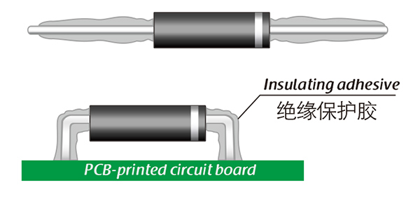
Here, suitable insulation adhesive materials can be selected based on the different usage situations of engineers.